356 with Midmounted Audi V8 - Build Thread
-
grant craft
- 356 Fan
- Posts: 56
- Joined: Sat Jan 02, 2010 9:36 am
-
Jim Nelson

- 356 Fan
- Posts: 2140
- Joined: Wed Mar 26, 2008 2:18 pm
- Location: SoCal
-
Mike Klapac

- 356 Fan
- Posts: 690
- Joined: Thu Apr 03, 2008 12:41 pm
-
Trevor Gates

- 356 Fan
- Posts: 1094
- Joined: Thu Dec 10, 2009 6:52 pm
- Location: San Clemente, CA
-
grant craft
- 356 Fan
- Posts: 56
- Joined: Sat Jan 02, 2010 9:36 am
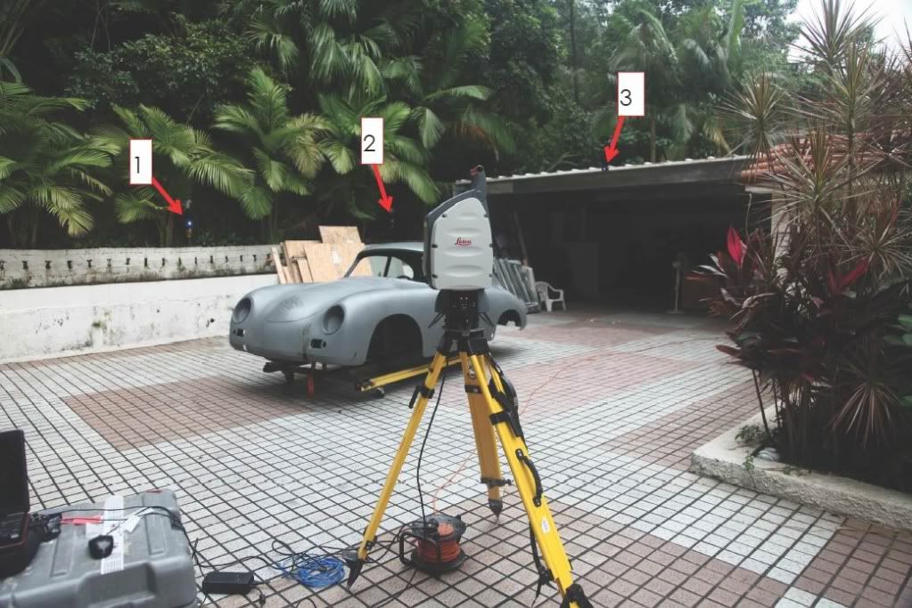
We started the scanning this weekend, here’s the setup.
The scanner sits on a tripod.
The scanner comes with a set of “Targets”, 3 of these are set up in fixed locations.
When the car is scanned, these 3 targets are also scanned and registered in the database.
Later, when we want to stitch together multiple scans, these 3 points are used to register each scan to the next.
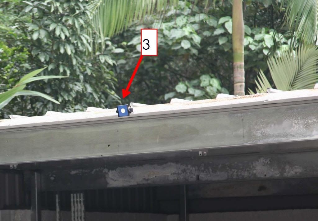
This is what they look like up close, when you “register” each of these targets the scanner does a very dense scan, and determines the X,Y,Z co-ordinate of the centre of the white dot.
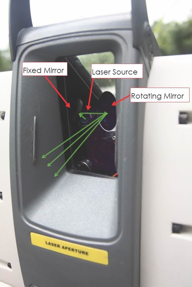
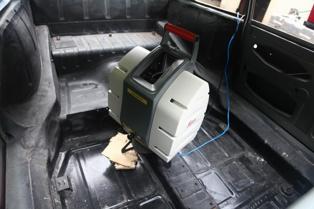
This is what the scanner looks like up close. The green line represents the path of the laser. The rotating mirror bounces the laser to the environment and measured X,Y,Z co-ordinates of the object it hits. The head of the scanner moves left to right.
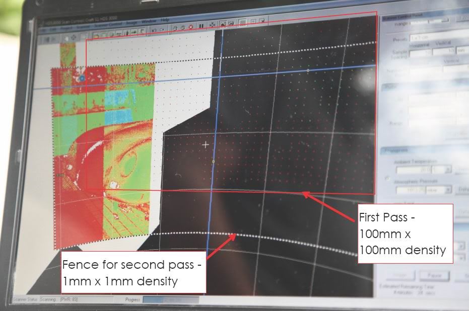
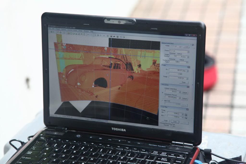
The first pass of the scanner was done at 100mm x 100mm, this is to make sure the scanner is aiming at the correct area. The redline indicates the fence we used for the first scan. As you can see, it didn’t pick up the lower part of the car.
The fence for the scan was then adjusted and a second pass was done at 1mm x 1mm.
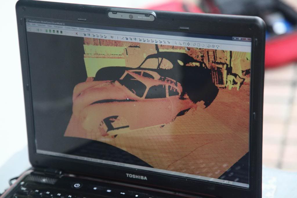
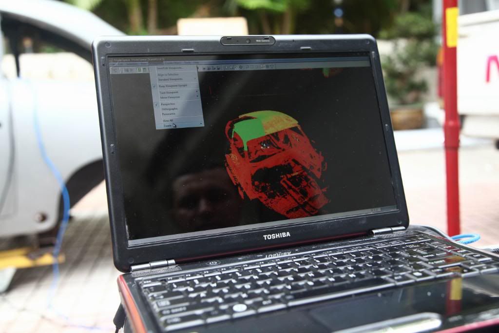
Here’s the finished scan from the second pass.
Here’s another view of the scan from the first location. In the image above, you are looking at the data from the angle that the data was scanned.
If we rotate the data slightly, you can see that there is a “shadow” behind the objects.
The data is called a “point cloud”, it’s a series of points that are the X,Y,Z co-ordinates of each shot that the laser fired.
This scanner shoots 4,000 points per second.
This particular scan took about 15 minutes….. so its about 3,600,000 points.
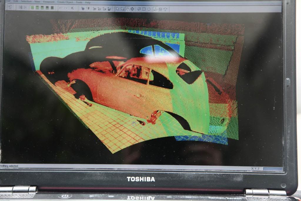
Next step is to move the scanner around to the rear of the same side of the car. As before you can see the more dense information is being written over the initial (less dense) scan… a little of the less dense scan is visible at the rear of the car. The 3 targets are also scanned with the scanner in this location.
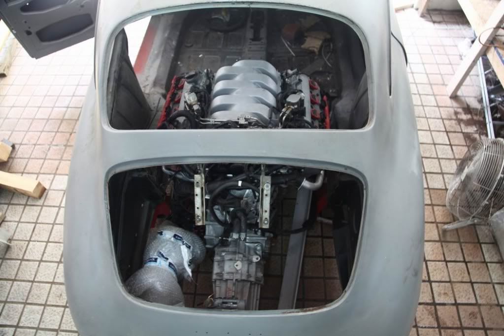
Then we moved it inside the car.
You can see that there is a lot of extra data (ground, trees etc) in the scan. When we register all the scans together we will cut out this extra rubbish
After the data is cleaned up, we’ll convert it into a mesh. Basically the points are joined together into a series of triangles, the mesh can then be brought into Solidworks and we can start detailing the chassis etc.
We didn’t get around to scanning the engine and trans, the scanner started to get a connection error that was pissing us off, hopefully it is the cable.
We did however rip the Quattro (AWD) box off and put the 2WD box on.
We struggled for an hour or so trying to get the engine and trans separated.
We had the engine on an engine hoist, at the trans supported on a chain block.
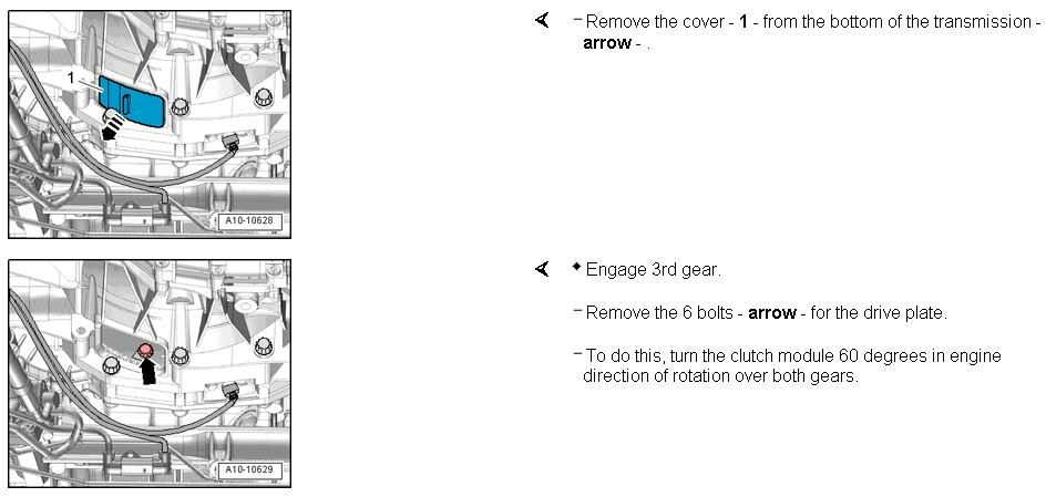
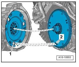
No matter what we tried we couldn’t get the XXXing thing off the engine…….so as a last resort we looked at the workshop manual and found that Audi have a flexplate and ring gear bolted to the crank, and the flywheel is bolted to the flexplate…….so when you separate the trans from the engine, the flywheel and clutch stay with the trans.
Audi’s have the engine north/south in both the front wheel drive cars and the AWD cars. The AWD box has 2 output shafts on the side for the front wheels and one out the back that goes to a rear diff. Check out the difference in size, the Quattro box is huge.
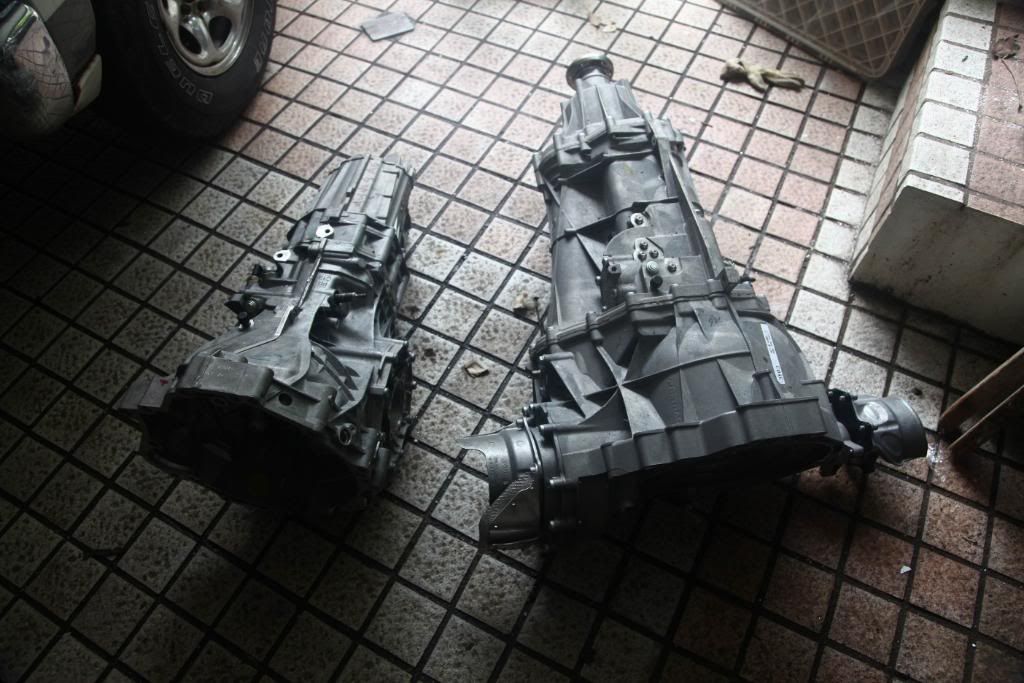
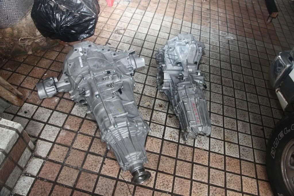
All in all, a good start. We now have the 2WD box fitted to the engine, the great news is that the bolt pattern is the same, from checking around the net it seems that the earlier RS4 clutch and flywheel will work, I’ve sent out emails to 3 companies and waiting for a response.
We’ll be cleaning up the scans this week and I’ll post a cleaned up model.
The scanner sits on a tripod.
The scanner comes with a set of “Targets”, 3 of these are set up in fixed locations.
When the car is scanned, these 3 targets are also scanned and registered in the database.
Later, when we want to stitch together multiple scans, these 3 points are used to register each scan to the next.
This is what they look like up close, when you “register” each of these targets the scanner does a very dense scan, and determines the X,Y,Z co-ordinate of the centre of the white dot.
This is what the scanner looks like up close. The green line represents the path of the laser. The rotating mirror bounces the laser to the environment and measured X,Y,Z co-ordinates of the object it hits. The head of the scanner moves left to right.
The first pass of the scanner was done at 100mm x 100mm, this is to make sure the scanner is aiming at the correct area. The redline indicates the fence we used for the first scan. As you can see, it didn’t pick up the lower part of the car.
The fence for the scan was then adjusted and a second pass was done at 1mm x 1mm.
Here’s the finished scan from the second pass.
Here’s another view of the scan from the first location. In the image above, you are looking at the data from the angle that the data was scanned.
If we rotate the data slightly, you can see that there is a “shadow” behind the objects.
The data is called a “point cloud”, it’s a series of points that are the X,Y,Z co-ordinates of each shot that the laser fired.
This scanner shoots 4,000 points per second.
This particular scan took about 15 minutes….. so its about 3,600,000 points.
Next step is to move the scanner around to the rear of the same side of the car. As before you can see the more dense information is being written over the initial (less dense) scan… a little of the less dense scan is visible at the rear of the car. The 3 targets are also scanned with the scanner in this location.
Then we moved it inside the car.
You can see that there is a lot of extra data (ground, trees etc) in the scan. When we register all the scans together we will cut out this extra rubbish
After the data is cleaned up, we’ll convert it into a mesh. Basically the points are joined together into a series of triangles, the mesh can then be brought into Solidworks and we can start detailing the chassis etc.
We didn’t get around to scanning the engine and trans, the scanner started to get a connection error that was pissing us off, hopefully it is the cable.
We did however rip the Quattro (AWD) box off and put the 2WD box on.
We struggled for an hour or so trying to get the engine and trans separated.
We had the engine on an engine hoist, at the trans supported on a chain block.
No matter what we tried we couldn’t get the XXXing thing off the engine…….so as a last resort we looked at the workshop manual and found that Audi have a flexplate and ring gear bolted to the crank, and the flywheel is bolted to the flexplate…….so when you separate the trans from the engine, the flywheel and clutch stay with the trans.
Audi’s have the engine north/south in both the front wheel drive cars and the AWD cars. The AWD box has 2 output shafts on the side for the front wheels and one out the back that goes to a rear diff. Check out the difference in size, the Quattro box is huge.
All in all, a good start. We now have the 2WD box fitted to the engine, the great news is that the bolt pattern is the same, from checking around the net it seems that the earlier RS4 clutch and flywheel will work, I’ve sent out emails to 3 companies and waiting for a response.
We’ll be cleaning up the scans this week and I’ll post a cleaned up model.
-
Damon Gawley
- 356 Fan
- Posts: 14
- Joined: Tue Oct 13, 2009 11:48 am
Dude that is cool, but very confusing; if the reference points are outside the car, then you moved the camera to shoot inside, haven’t the reference points changed? I can’t get my head around how you stitch those two models together. Seems like you might create a time/space infinite loophole in which case the car could theoreticaly exceed the speed of light.. Where are you planning to mount the flux capacitor?
-
grant craft
- 356 Fan
- Posts: 56
- Joined: Sat Jan 02, 2010 9:36 am
-
Terry Nuckels

- 356 Fan
- Posts: 34
- Joined: Sat Apr 05, 2008 8:52 pm
- Location: Grass Valley, CA
-
Mike Klapac
- 356 Fan
- Posts: 690
- Joined: Thu Apr 03, 2008 12:41 pm
-
Vic Skirmants

- Registry Hall of Fame
- Posts: 9300
- Joined: Tue Oct 27, 2009 5:02 pm
- Location: SE Michigan
- Contact:
-
Roy Smalley
- 356 Fan
- Posts: 598
- Joined: Wed Mar 26, 2008 10:43 am
- Location: North East Texas
Dang, I am tired
Time for a rest.....
Where in the world do you get all this energy?
Kinda mind blowing for an old body man.......
Where in the world do you get all this energy?
Kinda mind blowing for an old body man.......
Roy Smalley
Texas
Texas
-
grant craft
- 356 Fan
- Posts: 56
- Joined: Sat Jan 02, 2010 9:36 am
-
Erik Thomas
- 356 Fan
- Posts: 403
- Joined: Thu Jan 14, 2010 4:55 pm
- Location: Rhode Island
Grant:
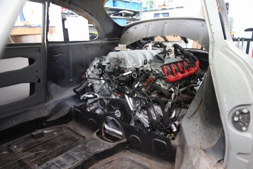
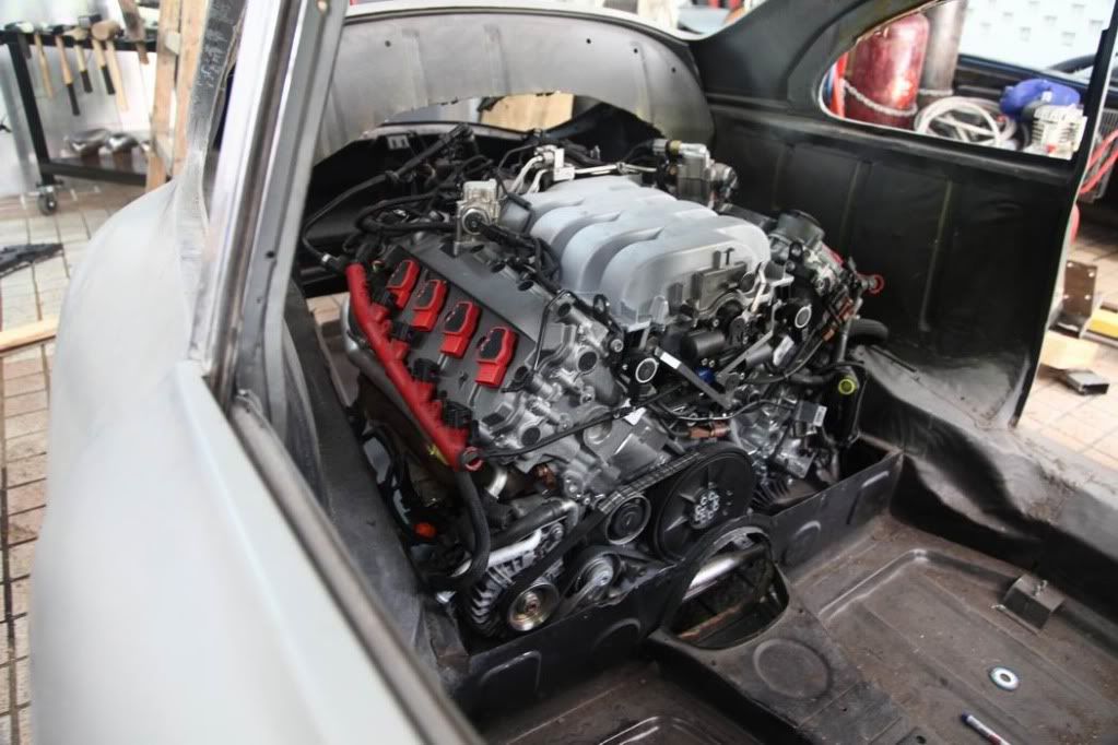
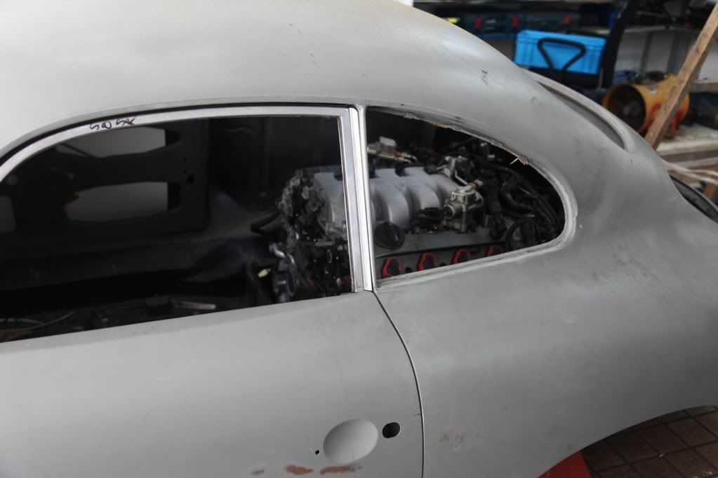
While it is not going to win any SAE award for wrench clearance, it does indeed fit in there very nicely.
Looks like you could make a box that covers it, would hardly know it was in there.
Using the stock cooling air intake location, I think there is room over the transmission for a force fed radiator. This would make for less complications than front mounted, IMHO.
Sorry I missed you in HK last month, see you next trip.
-
Jack Stenner

- 356 Fan
- Posts: 144
- Joined: Sun Mar 09, 2008 4:14 pm
- Location: Gainesville, FL
- Contact:
-
grant craft
- 356 Fan
- Posts: 56
- Joined: Sat Jan 02, 2010 9:36 am
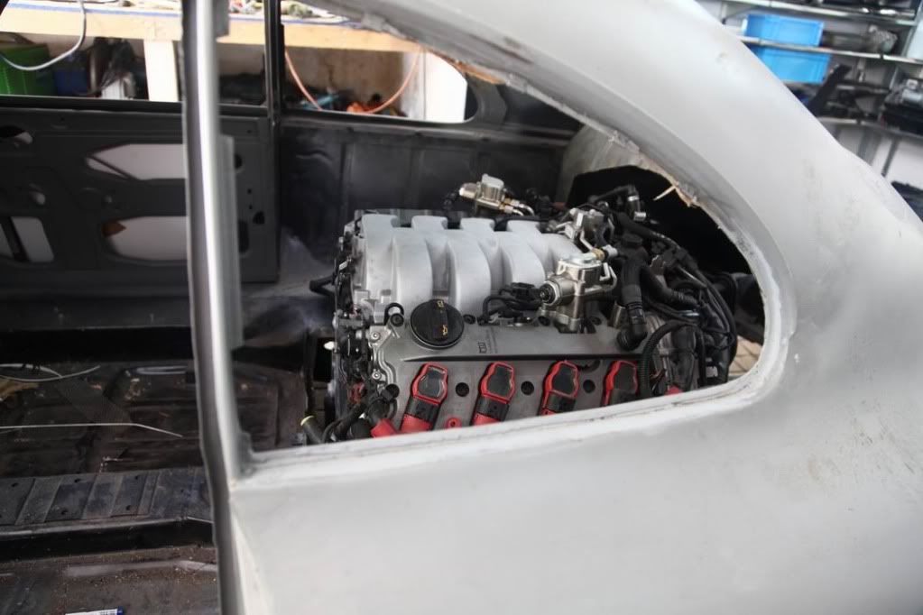
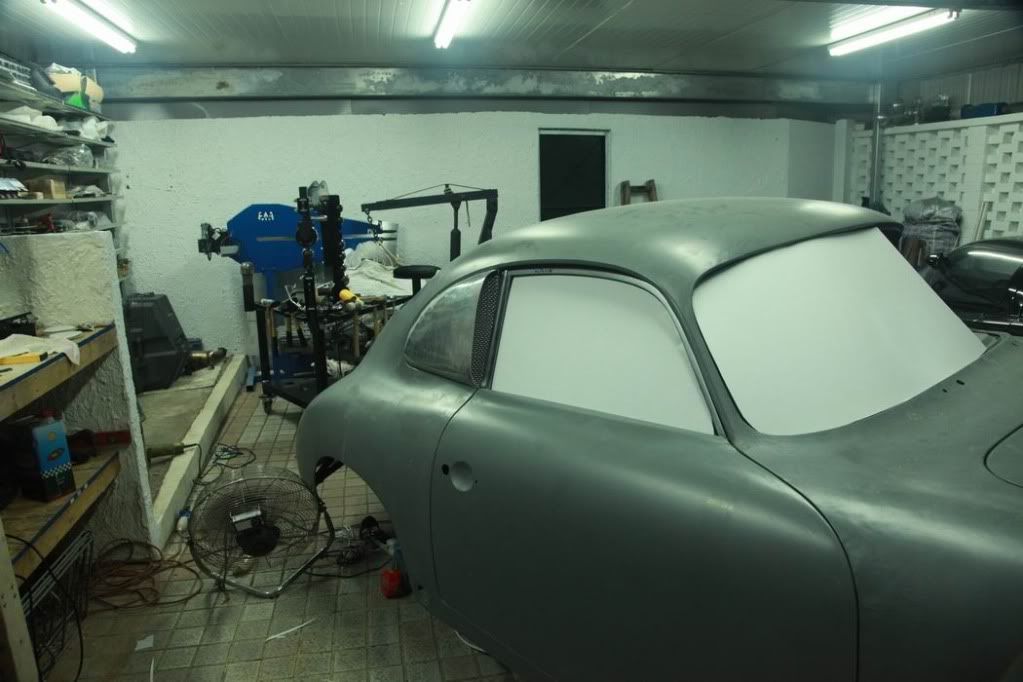
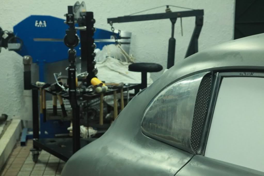
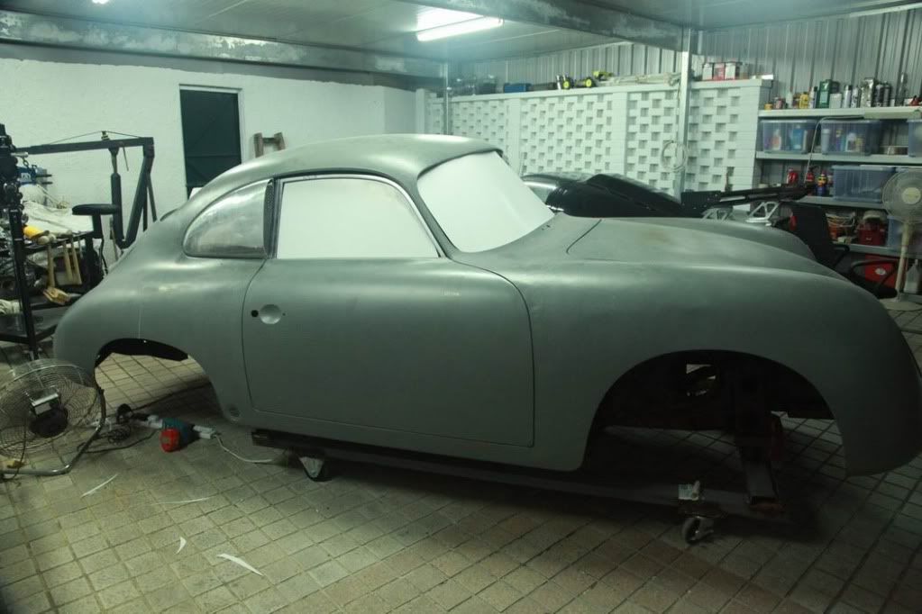
... here's another few shots from a couple of weeks back. I bought an English wheel and a load of other metalworking tools that were shipped with the car from USA.
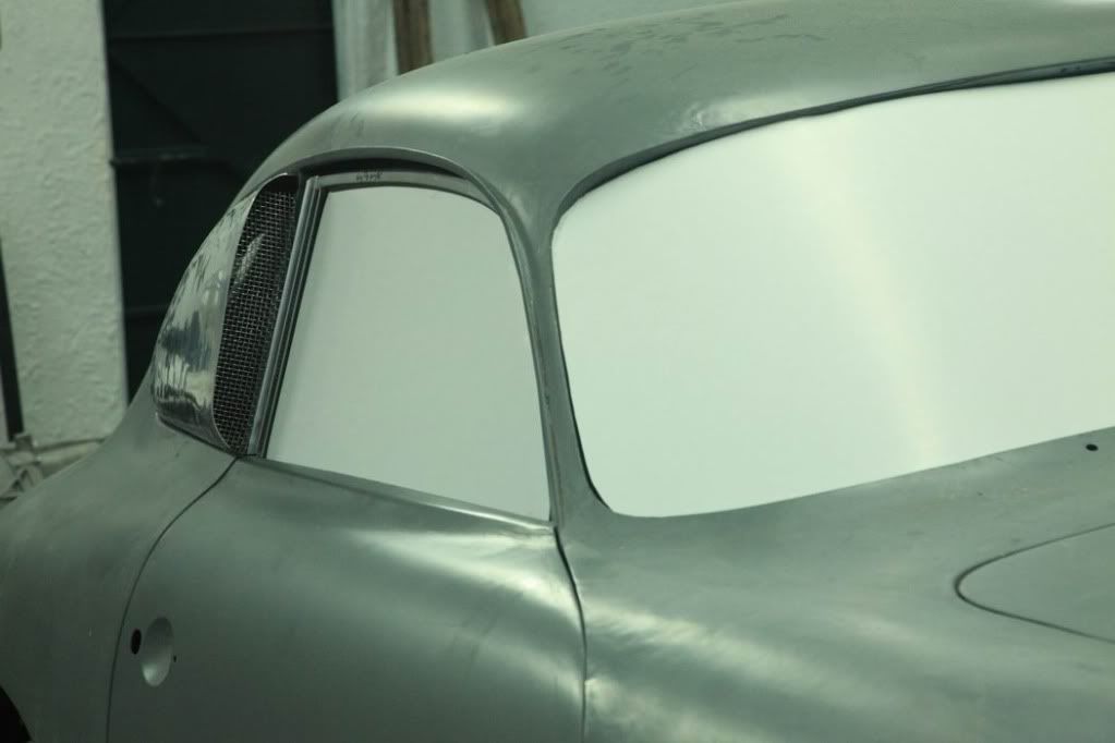
This is a first draft and obviously still needs work to get it properly shaped, its not trimmed properly at the front either and the mesh is just pushed in there... I'm going to rough out one side of the car with a few different options before I decide which shape I will use for the scoop.
I think the drip rail has to go.
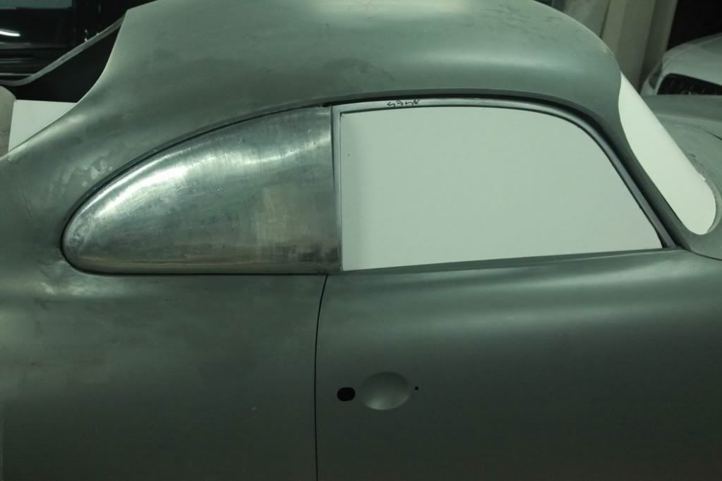
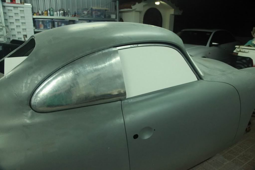