Page 5 of 12
Re: Holiday ride of shame
Posted: Sat Nov 09, 2019 12:26 pm
by Martin Benade
Ron and I were referring to the website. Seems better today.
Re: Holiday ride of shame
Posted: Sat Nov 09, 2019 1:48 pm
by Al Zim
In order to properly measure the height of the cylinder you will need to take it to a machine shop. they will need a granite table and a dial indicator. Clean the top sealing surface on 400 grit paper on a thick piece of glass. That will insure the cylinder is flat against the granite table. Then he will be able to measure the base of the cylinder with a dial indicator to check the consistency of the demention. Then with a pair of vernier calipers (read big) he should be able to check the length of the cylinder. This cannot be done at home with a tape measure! al zim
Re: Holiday ride of shame
Posted: Sat Nov 09, 2019 2:04 pm
by Dick Weiss
Dan,
Your photos show that the cylinders (all four) were sitting on the shoulders of the top fin and NOT
on the cylinder ends to the seats in the chambers; If fly-cutting was done, the head face(s) should've
been cut to the proper depth/relationship (9,5-9,7mm) to clear the shoulders.
Recheck the cylinders that the HEIGHT of the top ends exceed the above dimension & the seat-lengths
are equal w/.0005"; During assembly, you should see a small gap between the faces mentioned.
By the way, fly-cutting the heads should be matched equally w/in .0005"-.0008" about 6" in both planes.
Dick
Re: Holiday ride of shame
Posted: Sat Nov 09, 2019 3:49 pm
by Martin Benade
I think the top fin area was machined, that was my clue that the cylinder sealing surface had been cut too. I doubt if it would have made 10,000 miles seated on the fins.
Re: Holiday ride of shame
Posted: Sat Nov 09, 2019 4:51 pm
by Dan Epperly
Dick Weiss wrote: ↑Sat Nov 09, 2019 2:04 pm
Dan,
Your photos show that the cylinders (all four) were sitting on the shoulders of the top fin and NOT
on the cylinder ends to the seats in the chambers; If fly-cutting was done, the head face(s) should've
been cut to the proper depth/relationship (9,5-9,7mm) to clear the shoulders.
Recheck the cylinders that the HEIGHT of the top ends exceed the above dimension & the seat-lengths
are equal w/.0005"; During assembly, you should see a small gap between the faces mentioned.
By the way, fly-cutting the heads should be matched equally w/in .0005"-.0008" about 6" in both planes.
Dick
Hi Dick,
I put the cylinders in the head and using a flashlight you can see they are not resting on the shoulders of the cylinders but are contacting inside the combustion chamber.
For shits and giggles, while the cylinders were still in the head, I took a straight edge and laid it across number two, then slowly pushed it toward number one cylinder. The straight edge struck the side of number one.
I then laid it across number one and slowly slid it toward number two, it passed over the rim of number two easily.
I took a marker and marked up the surface of number two and moving the straight edge back in forth while on number one tried to see if I could remove any material, didn't touch it.
Yes, in know this isn't scientific and I will have the machinist measure, but looks to me like I might have found my problem.
Re: Holiday ride of shame
Posted: Sat Nov 09, 2019 4:51 pm
by Ron LaDow
Dick Weiss wrote: ↑Sat Nov 09, 2019 2:04 pm
Dan,
Your photos show that the cylinders (all four) were sitting on the shoulders of the top fin and NOT
on the cylinder ends to the seats in the chambers; [...]
Dick
Dick, I missed that; I think you got it.
Compare:

- th.jpg (19.33 KiB) Viewed 1664 times
to:

- 1967285.jpg (428.49 KiB) Viewed 1664 times
That arrow is showing the line at the edge of the fin 'land' on the cylinder.
It's also easy to check: Drop a cylinder into a corresponding chamber and check for clearance with a feeler gauge. Pretty sure you'll find none.
Re: Holiday ride of shame
Posted: Sat Nov 09, 2019 5:18 pm
by Martin Benade
Dan had already found clearance at the fin area
Re: Holiday ride of shame
Posted: Sat Nov 09, 2019 5:34 pm
by C J Murray
The recess that Ron points our with the red arrow appears to have been machined and I am guessing that there is clearance there when assembled since there is carbon covering it where the leaks are. The fins were not making contact. I admit I have never seen a head relieved that way as the correct way is to machine the entire surface from one end of the head to the other.
Measuring the lengths of the cylinders is easily done with a common caliper, usually a dial type. You don't need to be a machinist.
There is a spec for the maximum amount deep a head can be cut at the cylinder sealing surface but some liberties can be taken as long as you have clearance for the fins or make clearance. Ron is right to point out the secondary combustion chamber in his drawing but in a street engine with sensible pumping pressures there is not likely to be any problems caused. Machining the squish portion of the chamber can be problematic too. With 60 year old parts you have to be a little flexible.
Re: Holiday ride of shame
Posted: Sat Nov 09, 2019 7:39 pm
by Al Zim
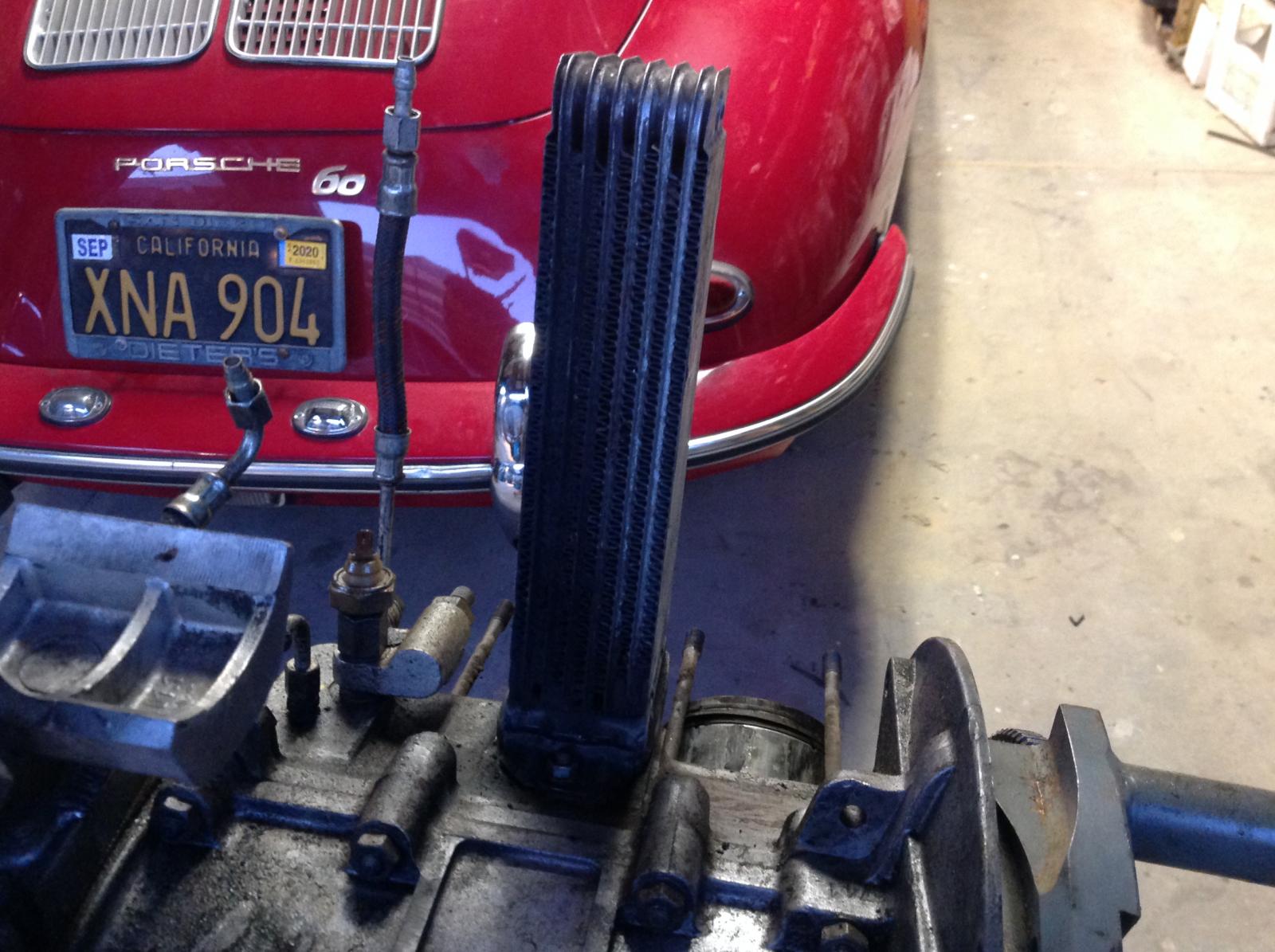
If you are using digital vernier calipers you can get a measurement on the side of the cylinder that has the short fins. These measurements are in very small increments I would suspect that your $19.95 calipers probably leave a lot to be desired. Probably this post would not be here if the proper measuring tools and the shop manual were present in the assembly of the engine. Metal particles may have been floating in the engine! With each revolution they ground material off the camshaft, lifters and bearings on the crank. These particles have crept into the oil cooler and into the passages on the engine block. If you cannot TOTALLY clean the insides of (read areas where oil flows) the engine then there is really no sense in putting it back together.
Re: Holiday ride of shame
Posted: Sat Nov 09, 2019 9:01 pm
by Dan Epperly
Re: Holiday ride of shame
Posted: Sat Nov 09, 2019 9:06 pm
by Martin Benade
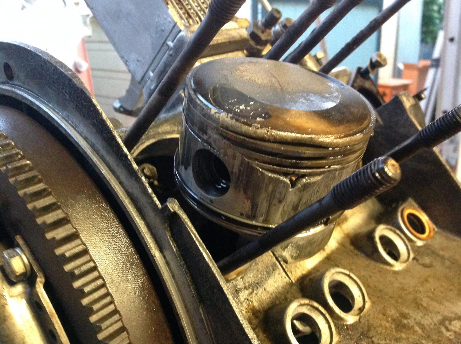
That’s your dead miss, the leaking head is excellent compared to that melted piston.
Re: Holiday ride of shame
Posted: Sat Nov 09, 2019 10:00 pm
by C J Murray
Looks like we are heading back to a discussion about detonation.
And your actual measured CR was what?
What cam?
Re: Holiday ride of shame
Posted: Sat Nov 09, 2019 10:34 pm
by Dan Epperly
C J Murray wrote: ↑Sat Nov 09, 2019 10:00 pm
Looks like we are heading back to a discussion about detonation.
And your actual measured CR was what?
What cam?
I set it at 8:5
It was a NOS B cam came with the car.
Always ran premium in it. Set the timing with a gun even double checked with a dial in type gun before we drove to Flagstaff.
No. 3 was the only one that looked like this.
The oil cooler was partially partially blocked with gunk, the day it failed we drove up a 5k mountain from sea level at 100 degree. Temps...
Re: Holiday ride of shame
Posted: Sat Nov 09, 2019 10:53 pm
by Ron LaDow
Cliff,
I guess they are recesses; NEVER seen a head relieved in that manner.
Dan,
The #3 and #4 images are exactly what might have been caused by that overhang and the local, *very* high CR.
Re: Holiday ride of shame
Posted: Sat Nov 09, 2019 11:23 pm
by Martin Benade
The 36 Hp VW engine in my first B got one piston looking that way from 20 minutes on the freeway with no belt. I was young and dumb enough not to have a working generator light!